
We will first define the analog and digital pins that we have connected with the VRx, VRy, and SW pins of the Joystick module. Serial.println (button_State) // Printing the button is high or low on the displayĭelay (1000) // This will add delay between readings Serial.print (" | Button State is ") // Printing “ Button state ” on the display

Serial.print (y_Position) // Printing value of y key on the display Serial.print (" | Value of Y key is ") // Printing “ Value of Y key is ” on the screen Serial.print (Horizontal_Position) // Printing value of x key on the display Serial.print (" Value of X key is ") // Printing “ Value of X key is ” on the display Y_Position = analogRead (y_key) // Reading the value from A1 and storing in y_Positionīutton_State = digitalRead (Push_Button) // Reading the digital pin 2 is high or low Horizontal_Position = analogRead (x_key) // Reading the value from A0 and storing in Horizontal_Position If you have Arduino version previous to Arduino 1.0.1, then use these commands for activating pull-up resistor. PinMode (Push_Button, INPUT_PULLUP ) // This will activate pull-up resistor on the push-button pin PinMode ( y_key, INPUT ) // Selecting Arduino analog A1 pin as input PinMode ( x_key, INPUT ) // Selecting Arduino analog A0 pin as input
#Servo motor arduino tutorial serial#
Serial.begin (9600) // initializing serial communications at 9600 bps: Int button_State = 0 // Declaring a variable for storing the value Int y_Position = 0 // Declaring a variable for storing the value Int Horizontal_Position = 0 // Declaring a variable for storing the value Int Push_Button = 2 // initializing digital pin 2 for joystick’s press to select button Int y_key = A1 // initializing A1 for storing the joystick’s y key value int x_key = A0 // initializing A0 for storing the joystick’s x key value Moreover, the switch output will be shown as well. This sketch will display on the serial monitor, the Joystick physical positions in terms of x and y coordinates. Open your Arduino IDE and go to File > New to open a new file. The values of VRX, VRY, and SW changes according to the picture shown below.Īrduino Sketch: Reading analog/digital input from Joystick Module When we press it in the middle position, the SW pin becomes high. When we move it in diagonal direction values of both VRX and VRY vary. When we move this module up or down, the value of VRY varies.

When we move joystick module on the left or the right side value of VRX varies. Only these analog pins of Arduino can be used to measure analog signals. They have 5 built-in analogs to digital converter channels. Analog pins in the Arduino board are marked with the letter ‘A’ e.g. This change is measured through the ADC pins of the Arduino board. The resistance of the potentiometer changes as the joystick’s physical position is varied. The position is interpreted as analog values from the Arduino board. They are used to determine the position of the rod. These two mechanisms make it easier to determine the position of the Joystick (right, left, up, and down) using the Arduino board.Įach potentiometer is connected to each of the Joystick’s shafts. The Joystick Module works on the basic principle of two potentiometers and a Gimbal Mechanism. One Potentiometer is for x-axis control and another Potentiometer is for Y-axis control. Variable resistors provide output in the form of analog voltage and push-button provides output in digital form either low state or high state. It consists of two variable resistors and a push button. The Joystick module is a very simple self-centered spring-loaded module similar to S2 (PlayStation 2). It can be used with many microcontrollers but we are using Arduino. The KY-023 Joystick module is the simplest to use module and it adds greater flexibility to your projects.
#Servo motor arduino tutorial how to#
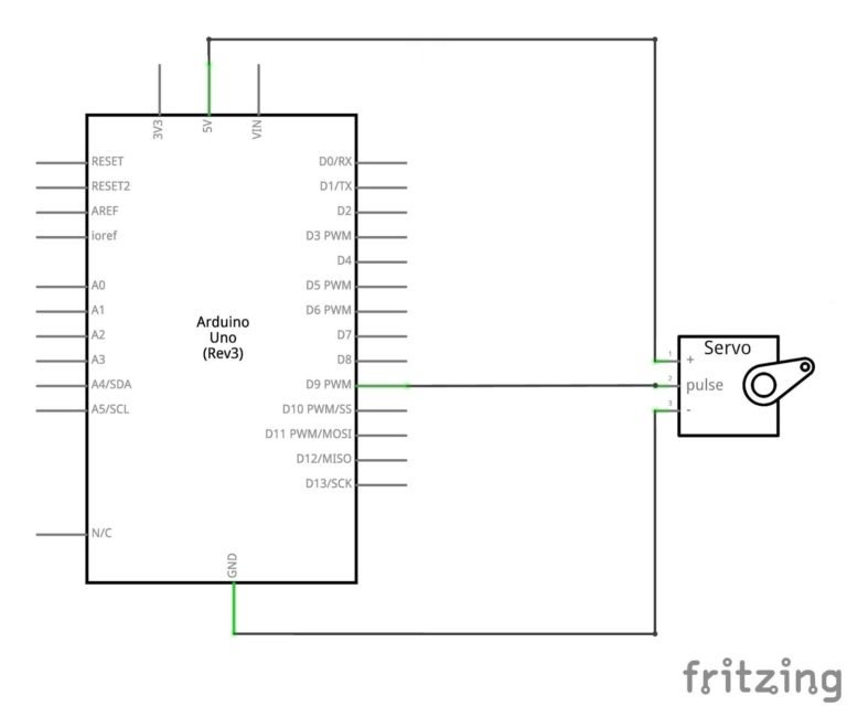
To design a joystick based servo motor control project, you should know how to use the joystick module and how to interface the servo motor with Arduino. The joystick we are using is analog and it provides more accurate readings than the simple directional joysticks. Firstly, we will first learn how to use joystick module and interface it with Arduino and then we will see an example of joystick based servo motor control by using two servo motors. In this joystick based servo motor control tutorial, we will control two servo motors using a joystick module and Arduino.


 0 kommentar(er)
